Basic features
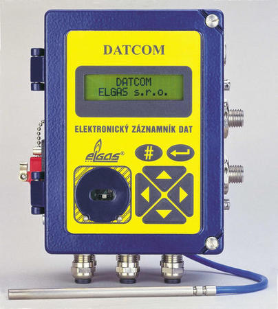
On the front side of a device there is placed a two-line alphanumeric LCD display (2 x 16 characters). In the frame of display there is placed the indicative LED diode. Below the display on right side there are six bottoms of foil keyboard for device control. On left side next to the keyboard there is a vane for optical communication head and for communication via IrDA® interface.
The device is constructed for use of pressure transducers of relative and absolute pressure as well. For connecting the binary signals there is determined the nine-pole connector at left wall of the cabinet of a Datalogger.
DATCOM is the "designated product" in terms of §12 of Law No. 22/1997 Code. It belongs to the group of "operating un-designated measuring instruments" in terms of Law No. 505/1990 of Code about metrology.
By help of in-built RS-485 interface there is possible the mutual interconnection of several Dataloggers into a local network. Such established local network of Dataloggers it is possible to connect by help of some communication module (which is a part of optional accessories) to the telephone modem (including GSM) or to radiomodem. Inbuilt Datalogger SW enables the generating of alarm signals and to transfer them to a superior system.
By the part of Datalogger is a programming equipment for PC computer. By help of this programming equipment there is possible to read / count the momentary measured values, and data to be recorded in Datalogger archives into a PC computer.
Communication PC with Datalogger it is possible to perform technically via any inbuilt DATACOM interface, it means via RS 232, RS 485, via optical head or via IrDA® interface. Delivered programming equipment therewithal serves for setting up the Datalogger parameters.
Overview and functions
Datalogger DATCOM ensures the basic functions:
- measurement of momentary values of input quantities
- archiving of momentary values or calculated statistical values
- securing the communication and data transfer between the Datalogger and the type of PC computer or by another computing system
In full mounting the DATCOM enables the following:
- measuring of two pressures (if need be the temperature)
- temperature at the place of probe
- device internal temperature
- counting impulses from two impulse sensors with flow evaluation and the accession of standardised volumes and to process the conditions of binary inputs
Measured quantities are periodically stored into the integrated data archive. Into this archive can be stored the momentary measured values or calculated statistical values. The measured values or data from archive can be transferred via communication interface into a computer.
Although from outside DATCOM appears to be a compact device, from the peripheral point of view this device consists of two parts. Measurement and storage part with communication possibilities are both controlled by stand-alone processor.
- Measurement part uses operational memory RAM and memory EEPROM for data storage and for storage of measured and calculated values. After filling up those operational memories are data transferred into storage and communication part.
- Storage and communication part use type of memory FLASH for data storage and for all its controlling and communicating processes. That memory enables cooperation with processor of communication channel control, as is communication with operation via display and keyboard, but also entire communication with connected devices. Another advantage of this memory is its very simple exchange of controlling communication SW, without necessity of intervention into device.
Connection of binary input is realized by 9 pin connector. Direct connection of signal from binary sensors into this connector is feasible, if all the signals are carried in one cable. With more signals is necessary to use multiple modules DATCOM-R1 or DATCOM-R2 (delivered as accessories).
Measurement of analogue signals as are pressure and temperature is conducted periodically with set measurement period. Measurement period is set for each measured input separately.
Impulse inputs - standardly one impulse input for connecting contact of gas meter. It is also possible to connect another second impulse input. For this one is used binary input B1, which is configured by software.
Binary inputs - eight binary inputs B1 to B8 split into two groups according to evaluation method. For each binary input is defined its requested active level. During reaching active level can be generated alarm signal.
- Inputs B1 to B4 - so-called fast inputs, change of condition is evaluated immediately
- Inputs B5 to B8 - so-called slow inputs, detection of condition of those inputs proceeds cyclically with reading binary inputs period 30 s
For each binary input is defined its requested active level. During reaching active level can be generated alarm signal.
Data storage
Momentary values of each input can be displayed on display of datalogger or on monitor of connected PC. From measured momentary values can also DATCOM compute statistical values (mean value, maximal and minimal value etc.) for a given period. Measured momentary values, or calculated statistical values can be stored into internal archive.
DATCOM has inbuilt following archives for storing measured data and other auxiliary data:
- daily archive
- limit archive
- status archive
- fast archive
Data archive stores time shots of measured quantities that is storing momentary measured or calculated statistical values of measured quantities with record period.
Record period is set for each measured quantity separately. In a case of binary input are into this archive entered conditions changes of any binary inputs with corresponding time stamp.
Daily archive is used for storing resulting values of measured (more accurately stored) quantities in individual days. Daily archive is calculated in the moment of displaying its data on display of datalogger from data in data archive and can not be read via communication line as any other archives. Values in daily archive are dependent on setting of the beginning of gas day.
Limit archive does not contain any time flow of quantities, but only one maximal and minimal value for each analogue input (pressure1 P1, pressure2 P2, temperature T) and one max. value of operational flow (Q1, Q2) for each impulse input (I1, I2). Data in limit archive are recorded from the last zeroizing of limit archive. This zeroizing of limit archive can be conducted from utility program DATCOM.EXE started on the computer PC. With each recorded value in archive is given time of its occurrence.
Status archive is intended for storing information about important datalogger states.
- exceeding any measured momentary values of analogue signal over some set limit
- occurrence of hardware error of any pressure or temperature transducer
- occurrence of some hardware errors of device
- feeding error from inbuilt battery
- failure of commercial power supply during feeding from an external source
- occurrence of any from a generated alarms
During occurrence or termination of any of the given facts is in archive created record about that event. In archive is recorded date and time of event occurrence and its brief name. If some event already lasts and another occurs, new record is made into archive. In this record are contained information about new event as well as about momently lasting events.
Fast archive - is a special type of archive for time monitoring of flow of one of the pressure channel with special switching regime. This archive serves for storage of measured momentary values only in some periods of time. It can also be used as auxiliary archive for one of the pressure input. Record into this archive is conducted with measurement period and is started only by fulfilling of the so-called starting conditions. Definition of starting conditions conducts user during setting parameters of datalogger via PC.
Starting of fast archive can be derived from:
- exceeding any of the set limit
- exceeding pressure gradient (that is speed of pressure change in time)
- state transition of one or more binary signals into active level
During fulfilling starting conditions are into fast archive stored measured momentary values of particular period of time shortly before fulfilling starting condition and momentary values from the following period of time after fulfilling starting conditions. Here is recorded state shortly before and after occurrence of some event. This archive can be used for instance for failure state analysis of measured system.
Communication
In this part are described technical communication possibilities, which do not take into account requirement for keeping service feature in a hazardous area. Datalogger is equipped with communication interfaces for communication with other devices.
Which are the following:
- RS 485
- RS 232
- optical head
- IrDA®
Next to standard way of communication, when connection with datalogger is initiated from the control computer (that means from above), initiates DATCOM alone in the case of alarm signal occurrence getting in contact with communication computer and sending alarm report.
Interface RS 485 is galvanically separated from datalogger circuit and is intended for mutual interconnection with other dataloggers or other devices and for connection of communication modules. Communication modules ensure communication of one datalogger or more interconnected dataloggers with computer either directly, or via modem connection.
Busbar RS 485 requires its own feeding, which can not be obtained by datalogger and is therefore secured by communication module. For realization of bus method interconnection are therefore in datalogger terminals for feeder cable and cable for connection to other datalogger.
Interface RS 232 is again galvanically separated and is intended for direct connection of one of datalogger with computer.
-
With datalogger can be simultaneously communicated max. via two interfaces:
- via RS 485 and with one of its interfaces RS 232
- optical head or IrDA®
-
For securing electrical energy savings and thereby extension of internal battery usage, is activated putting out some of circuits, which are not in a given period of time needed for the proper function of device. Therefore is prolonged time of device usage without battery exchange min. for 6 years.
During use of IrDA® is necessary to activate this interface by command from keyboard of datalogger.
-