Description
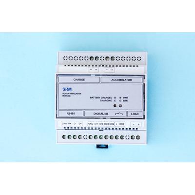
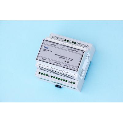
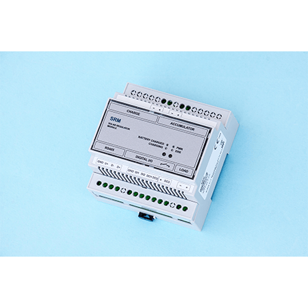
The Solar regulator is placed in a plastic box and is designed for installation into a rack on DIN 35 mm rail.
The SRM controller includes the controller circuitry to control the charging of the connected VRLA lead-acid battery, as well as the digital output extension circuit and the controlled semiconductor switch circuit.
The SRM Solar Controller is designed to charge a lead-acid VRLA battery from a solar panel or DC power supply. The accumulator serves as a source of external power and 12 V voltage of the connected corrector (recorder) and its accessories.
The SRM contains two inputs (DI1, DI2), which can be configured as pulse low frequency (LF) inputs or binary inputs (by default, DI1 controls DO3). It also contains three digital outputs DO1, DO2, DO3. Digital outputs DO1 and DO2 can be configured as pulse, binary or analog (by default they indicate the charging status). DO3 is a semiconductor switch for switching the voltage from the SRM output (eg. switching the power supply of the modem).
It is possible to communicate with the SRM via the RS485 bus. Information about charging status, battery condition, temperature, etc. can be read from the device and all inputs and outputs of the controller can be read and controlled. The device is compatible with ELCOR series correctors.
Basic features
-
The backup power of the connected corrector or logger
-
Integrated charging controller for the connected VRLA lead-acid battery
-
12V output voltage to supply the intrinsically safe corrector power supply
-
2x digital input (LF pulse or binary input)
-
3x digital outputs (LF pulse, binary or analog output)
-
RS485 bus for communication with corrector or logger
-
Mounting on 35 mm DIN rail
-
Operating temperature is -40 to +70°C
-
Gallery